How to Revive Your Old Google Home Mini with a $85 PCB Upgrade for Local Processing
Introduction
Remember the Google Home Mini from 2017? It was the smallest and cheapest smart speaker Google ever made. Millions were sold, given as gifts, or handed out as promotional items. Even today, many of these devices still work for basic commands, but they lack modern capabilities like local processing and customizability. Google has since moved on—the Nest Mini is discontinued, and there are whispers of new Gemini-powered speakers. But what if you could bring your first-generation Home Mini into 2026 with local processing, all for just $85?
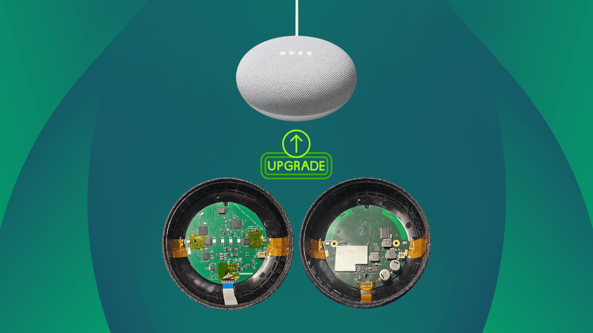
This guide walks you through upgrading your old Google Home Mini using the MiciMike Home Mini PCB. This tiny board replaces the original internals with an Espressif ESP32-S3 main processor and an XMOS XU316 audio chip. You'll get local voice processing, Wi-Fi/Bluetooth connectivity, and integration with Home Assistant—all while keeping your device's original hardware. Follow these steps, and you'll have a smart speaker that respects your privacy by processing voice data locally.
What You Need
Before you start, gather these materials and tools:
- A first-generation Google Home Mini (check compatibility; only the model launched in 2017 works).
- The MiciMike Home Mini PCB (available for around $85).
- Small Phillips-head screwdriver (for disassembly).
- A spudger or plastic pry tool (to safely open the device without scratching it).
- FPC cable (included with the PCB) to reconnect the original speaker.
- A computer for initial setup (optional, if you want to configure ESPHome).
- Home Assistant instance (recommended for full functionality, but not strictly required).
- Optional: Cloud LLM account if you want to use a remote AI agent for conversations.
Step-by-Step Guide
Step 1: Prepare Your Workspace
Choose a clean, well-lit area with enough room to lay out the small screws and components. It's easy to lose those tiny fasteners. Consider using a magnetic mat or a container with compartments to keep everything organized. Also, ground yourself to avoid static discharge that could damage the new PCB.
Step 2: Disassemble the Google Home Mini
Flip the device upside down. Locate the rubber base pad covering the bottom—gently peel it off with your pry tool. Underneath, you'll see four small screws (Phillips). Remove them and set them aside. Then, carefully separate the top cover from the main body. The microphones and speaker are attached to the top assembly. There's also a ribbon cable connecting the original PCB to the touch controls. Disconnect that ribbon cable by lifting the latch with your spudger.
Step 3: Remove the Original PCB
Once the top cover is detached, you'll see the original Google Home Mini PCB. It may be secured with a few screws or clips—remove them. Gently lift out the old board. Note the positions of wires and connectors (speaker, microphones, LEDs). You'll need to attach all these to the new MiciMike board later. The original power connector is soldered to the old PCB; you can cut or desolder the wires, but the MiciMike board typically requires you to connect a small power cable to its dedicated header. Consult the PCB's manual for the exact pinout.
Step 4: Install the MiciMike PCB
Place the new MiciMike board into the empty housing. It should fit snugly, with the components facing up. Use the included screw holes to secure it—the board may come with mounting screws, or you can reuse the original ones. Attach the FPC cable to the speaker connector on the board. The microphones on the top assembly also need to be connected. The PCB has two MEMS mic inputs aligned with the original positions. Use the small ribbon cables provided—or, if none are included, you can solder wires directly to the mic pads. Connect the LED ribbon (from the original device) to the SK6812 header on the board. Finally, attach the power wire from the original barrel jack to the power input on the MiciMike board (usually labeled 5V IN).
Step 5: Reassemble the Device
Place the top cover back onto the base. Feed the ribbon cable for the touch controls through the gap. Connect that ribbon to the new PCB's touch header. Ensure all wires are tucked inside and not pinched. The original mute button should line up with the hardware disconnection pin on the board—this completely isolates the microphones when pressed, just like on the original device. Press the top cover down until it clicks. Replace the four bottom screws and reattach the rubber base pad.
Step 6: Power On and Initial Check
Plug the power cable into the device. It should boot up within a few seconds. The four SK6812 RGB LEDs (in the same positions as the original) will light up as status indicators. If nothing happens, double-check all connections, especially the power wires. If you see a faint glow or no LEDs, re-seat the ribbon cables. A successful boot means the ESP32-S3 is alive, and the XMOS audio chip is ready.

Step 7: Configure the PCB (ESPHome and Home Assistant)
The MiciMike board comes with ESPHome preinstalled. This means it can work out of the box with Home Assistant, Music Assistant, and Snapcast. To get the most out of it, you need to configure the device on your network. Open a browser and go to http://micimike.local (or find its IP address via your router). You'll see a web interface. If you have Home Assistant, it should auto-discover the board. Add it as an ESPHome device. Then you can enable Assist for voice control. The wake word detection (microWakeWord) runs locally on the ESP32-S3, with no voice data leaving the device. For natural language conversations, you can optionally connect a cloud LLM (like OpenAI or Claude) as the conversation agent, but it's not required—you can use local text-to-speech and perform actions via Home Assistant.
Step 8: Test and Enjoy
Say the wake word (default might be "Hey Jarvis" or customizable in ESPHome) and test commands like turning on a smart light or asking for the time. The speaker should play responses clearly. Adjust settings like volume and LED brightness from the Home Assistant dashboard. The XMOS chip handles noise and echo cancellation from the two on-board microphones, ensuring accurate voice capture even in noisy environments.
Tips and Troubleshooting
- Soldering skills required? The MiciMike PCB is designed to be plug-and-play, but you may need to solder a few wires (e.g., power and microphone connectors). If you're not comfortable with soldering, ask a friend or check if the seller offers a pre-soldered version.
- Privacy first: The hardware mute button physically disconnects the microphones at the board level, giving you absolute privacy when you press it.
- LEDs are reference only: The four SK6812 LEDs mimic the original positions but can be customized via software (effects, brightness) in Home Assistant.
- Use the included FPC cable: Don't try to reuse the original ribbon for the speaker—it's different. Stick with the supplied one.
- Initial setup tricky? If the board isn't discovered in Home Assistant, set a static IP via your router, then manually add it as an ESPHome device.
- Check compatibility: This only works for the first-generation Google Home Mini (model GH-1000). Second-gen Nest Mini has different internals.
- Community support: Check online forums like the ESPHome or Home Assistant communities for custom configurations and firmware updates. The MiciMike board is open-source hardware (CERN-OHL-S license), so you can modify it.
With these steps, your old Google Home Mini becomes a modern, privacy-respecting smart speaker that processes everything locally. No more cloud dependence for basic commands, and you keep full control over your data. Time to give that dusty speaker a second life!